A detailed explanation of failure
of Sunvic motorised valves utilising valve actuator types SZM 1801 (two port) and SDM 1901
(three port) - Unishare types.
Following some initial assumptions about the reasons for
valve failure, I discovered in Feb 07 that intermittent faulty operation was caused not by
'burnt' points or other mechanical problems but by low operating voltage on the relay
coils within the valve actuators. The relays are 24 VDC types and yet the applied voltage
was variable between 12 and 14 volts. The pdf link for the relay type is here:
www.omron.com/ecb/products/pdf/en-g5sb.pdf
Data show that the model of relay G5S1 was discontinued in
March 2004, and replaced by G5SB. The "must switch-on voltage" is 75% of the
rated voltage whereas the applied voltage in the Sunvic valves was only about 12 volts, or
50% because these were 24VDC relays - therefore these designs of Sunvic motorised valve actuators become
unreliable because the voltage applied to the relay coils can fall well below that
guaranteed to operate the relay points -
perhaps because of a leaking electrolytic capacitor, perhaps because of a defective series
capacitor. Experience over 5 years has shown that it is invariably the series capacitor at
fault, the effective capacity being closer to 140nF rather than the rated 220nF. Later
actuators have a 330nF capacitor. Sunvic realised the problems that were occurring so they
added a reverse connected zener diode across the relay coil to limit both back emfs and
forward voltage. However, early failure of the 330nF types also occurs, especially in three port Unishare actuators.
The electrolytic capacitor is a cylindrical type, 63 volts 47 microfarad - these are quite
standard but have been known to degrade with time especially if used in hot conditions.
Any leakage would also have the effect of reducing the applied voltage across the relay
coil. This electrolytic, which is used for smoothing, has a hard life with large ripple
currents. The series capacitor was 220 nF rated at 275 volts (AC). Replacements MUST be to
a similar (X2) or higher specification - and 330nF (with a zener diode) to give the full
24 VDC across the relay coils.
Indeed, the fact that Sunvic changed these capacitors to a
value that gives over 30 VDC indicates that they knew of the degradation problem.
Combining a 330nF capacitor with a 24 volt zener diode would give an extended service
lifetime - because the capacitor could degrade for a year or more before the voltage drops
below 24V, and for a further year or more before the relay stops working reliably! A recent
report from ERA highlights that these failures may represent an early manisfestation
of an industry wide problem of poor quality capacitors - mirroring in a small way the
'capacitor plague' problem that caused maybe a billion dollars worth of electronics
equipment to be prematurely scrapped owing to inherent faults in electrolytic capacitors.
How the circuit works in a two port (1801 series) actuator:
The relay coil current is supplied via series connected C1
which drops most of the mains voltage, then the remaining voltage is rectified via the
bridge rectifier (these are generally very reliable) and then smoothed via C2 (47 microF).
When power is removed, the voltage across the relay decays as the charge on C2 reduces,
but this will be very rapid. The relay coil resistance is 1440 ohm, power 400mW, current
16.7 mA all of which has to come via C1.
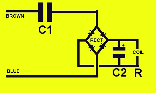 |
The live 240 VAC supply from
the thermostat (brown wire) is connected directly to one side of C1. This supplies a small
ac current to the bridge rectifier. The rectified (DC) voltage is crudely smoothed by
the electrolytic capacitor C2 which is connected directly across the 24 VDC relay coil
(R).
The voltage appearing across the coil (which must be at least 17 to 18 volts and
preferably 20 volts to ensure reliable operation) is crucially dependent upon the value of
C1 and also upon C2 not leaking. |
But why go to all the trouble of converting mains voltage
into rough 24VDC simply to operate a 24 VDC relay when you could surely use a 240 VAC
relay? The answer here seems to lie in the need to use compact and inexpensive DC relays
and the maintain the overall casing size so as to ensure interchangeability with earlier
actuator models.
You can get to the patent easily enough from the GB number (see emails) or this link might
work http://v3.espacenet.com/textdoc?DB=EPODOC&IDX=GB2393490&F=0
Testing of Sunvic valves of this
type may be performed as follows BUT BEWARE
YOU ARE DEALING WITH POTENTIALLY LETHAL MAINS VOLTAGE. Only highly experienced and
competent electronic hobbyists or professional engineers should attempt these tests. No
protection against electric shock will be afforded by a household RCCB (RCD) device
because any fault current (through you!) would likely be live to neutral rather than live
to earth. Indeed, you can get a mild shock from these capacitors even when the actuator
has been disconnected from the mains.
The valves can either be tested 'in situ' by utilising
power from the existing central heating circuit or (preferably) removed and tested on a
work bench. Simply connect a dc voltmeter across the relay coil (across C2 is the same
thing) and cause the valve to switch on. The coil voltage should be at least 18 VDC. If it
is wavering around 12 to 14 volts then replace C1. The bridge rectifier and the relay
itself only fail when the pcb allows high voltage tracking into low voltage lines, a
problem discussed elsewhere on this site. The microswitches and gearwheels have proven to
give relatively few problems. Failures of one or more of the microswitches may give
similar symptoms to those produced by degraded capacitors.
Nevertheless, the critical weakness of these actuators has proven to be the electronic
circuit design and/or the specification of components and pcb used. Over the years I have
received many helpful and supportive comments from electronic engineers, all of whom have
confirmed various views of the basic poor design of these actuators. Some of these
comments will be published later, including some from ex-Sunvic engineers.
Some insight into the tests applied to X and Y rated capacitors for use in mains
circuits can be obtained from many documents on the Internet. Here is one - copied from the RS website - in pdf
format. There seem to be no tests for how these capacitors degrade - indeed their
'self healing' characteristics when used in circuits with large voltage transients may
make them unusually prone to reduction in effective capacity, exactly what is not required
in the Sunvic circuits. Ceramic capacitors may be more stable over time but they do not
self-heal. This could have serious safety implications if they were used as a direct
replacement within Sunvic valves.
Finally, if repairing three-port (mid position Unishare) valve actuators of a similar
design it can be prudent to replace both the X2 type capacitors. These valves have three
interconnected microswitches which are unlikely to fail unless overloaded and should not
be disturbed. Power is supplied to the X2 rated capacitors not via a brown wire (as used
in two-port designs) but via grey and white wires. This is shown in the diagrams taken
from the patent website (link shown above). Three port Unishare valves regularly fail
after only a year or so in service: the reason for this is
explained here.
Better still, there are some clear typical system wiring diagrams in the Sunvic
catalogue - for convenience, the low resolution
version is available here: electrical wiring diagrams are on page 17 and typical
plumbing circuits on page 12. The zoom feature of Acrobat can be used as required. The
extra wires needed by the older Minival systems are clearly shown - these need a separate
motor-off command from the programmer (white wire) and they also have an earth connection.
In summary: within Sunvic valve
actuators, types SZM 1801 (two-port) and SDM 1901(three-port) the critical parameter is
the DC voltage across the internal relay coil(s). If this is too low, intermittent
unreliable operation of heating circuits will occur and may erroneously be blamed on other
system components. Also, if the circuit boards become even very slightly damp high voltage
will track through the pcb and destroy low voltage components, or (in the case of an 1801
actuator examined in March 2014) cause the motor to operate whenever power was applied to
the brown wire!
home page for Sunvic valves
home page of SeeRed